Monday, December 29, 2008

COM-BAT Spy-Plane

COM-BAT Spy-Plane

COM-BAT is a 6 inch robotic spy-plane that utilities a low-power mini radar and a high sensitive navigation system to help it find its way in the dark. “The bat” is also draws power from the sun, wind, vibration and other sources to recharge its battery. I think this robot will be used for military purpose in the future. [Product Page]

ApriPoko Robot Learns To Operate Remote Controls

ApriPoko Robot Learns To Operate The Remote Controls

The ApriPoko robot from Toshiba was developed to learn how to operate various remote controls by watching and asking questions. The robot features sensors that will be able to detect infrared rays coming out from the remote, so each time you press a button, ApriPoko will ask “What did you just do?”, so make sure you answer appropriately because it records your answer to its memory. This prototype robot is still in the development and testing phase. [PinkTentacle]

Thursday, December 18, 2008

AT89C2051 Real Time Controller

Introduction

This is my long history the device that controls my home's night light, air-conditioner, etc. The device is a Miniature Real-time Controller. The circuit uses only three chips, a 89C2051, DS275(or MAX232), and 74LS07 open collector driver. The scheduler for time on/off of 6-channel output can be made by downloading from PC and saved into onchip RAM. Each output provides a 20mA sinking suitable for driving a homemade opto-triac or big solid-state relay for heavy load.

Hardware

A circuit diagram of the Miniature Real-time Controller is shown in Figure 1. A 89C2051 with a low-cost X-tal 3.579MHz runs timer6.hex. The 6-channel output is P1.2 to P1.7 driving with sink current. A 74LS07 open collector provides approx. max 20mA @12V suitable for driving a homemade opto-triac shown in Figure 2. Two signal diodes, 1N914, provide simple backing up supply for the 89C2051. Since RST uses simple RC circuit, there is no brownout protection and reset switch thus when the controller operated with battery for long time, the chip may knock. Simply take the battery out and put them again. The RS232 level converter, instead of DS275, any converter may use, say MAX232, or simple circuit using two transistors.
Circuit Diagram of Miniature Real-time Controller
Figure 1: Circuit Diagram of Miniature Real-time Controller
(a nice circuit diagram was drawn by my student Patra Pienchob).

Homemade Opto-triac

An opto-triac with zero-crossing can be made easily. I have used an MOC3041 to drive 5A 240V triac. A night light used in my home mostly be an incandescent lamp, the circuit below works fine. For such heavy load as air-conditioner, I used a solid-state relay,one from CRYDOM D2410, say.
Example of Connecting homemade optotriac and SSR to the RTC.
Figure 2: Example of Connecting homemade optotriac and SSR to the RTC.


การควบคุบอุปกรณ์ไฟฟ้า ตามมาตรฐาน X10 ด้วย PIC16F628/PIC16F648


เป็นโครงงานที่ใช้ศึกษาการควบคุมอุปกรณ์ไฟฟ้าผ่านสาย AC-Line ด้วยมาตรฐาน X10 โดยมีวัตถุประสงค์ดังนี้

  • เพื่อศึกษาโปรโตคอลของ X10 และคำสั่งต่างๆ
  • monitor ข้อมูลที่ปรากฏบนสาย AC-Line พร้อมทั้งส่งเสียง และมีไฟกระพริบเมื่อได้รับคำสั่ง
  • สามารถรับคำสั่งผ่าน RS232 และส่งคำสั่ง ผ่านสาย AC-Line ไปยังอุปกรณ์อื่น
    - ทำให้สามารถเชื่อม เข้ากับระบบ ควบคุมอุปกรณ์ ไฟฟ้าผ่าน network อื่น เช่น RS485 ,TCP/IP โดยผ่าน LAN หรือ Internet
    - สามารถใช้โปรแกรม Application หรือ Browser ในการควบคุมหรือ monitor
  • เป็นแนวทางในการพัฒนาโมดูลอื่นๆ
    - ควบคุมอุปกรณ์ไฟฟ้าได้ 1 จุด เพื่อใช้ทดสอบการทำงานของคำสั่งผ่าน RS232 หรือโดยโมดูลอื่น
    - สามารถส่งสัญญาณ 120KHz แบบต่อเนื่องเพื่อใช้ปรับแต่งโมดูลอื่น
    - สามารถปรับความแรงในการส่ง เพื่อศึกษาและพัฒนาภาครับ ให้มีประสิทธิภาพ และทนต่อสัญญาณรบกวนอื่นๆ


พิจารณาความสามารถที่ต้องการจากโมดูลมาตรฐาน


รวมความสามารถของ โมดูลต่างๆไว้บนบอร์ดทดลอง X10LAB


  • X10LAB ได้มีแนวคิดที่จะนำความสามารถจากโมดูลมาตรฐาน
    - CM11U โมดูล Computer Interface-RS232 โมดูลเชื่อมต่อกับคอมพิวเตอร์
    - X10-4822 ภาคส่ง RF 433 MHz (จะพัฒนาต่อในระยะที่2)
    - 4022 Universal RF Base Transceiver ภาครับ RF 433 MHz (จะพัฒนาต่อในระยะที่2)
    - Appliance Module ชุดควบคุมอุปกรณ์ไฟฟ้า 1 จุด


วงจรชุดทดลองแบ่งออกเป็น 3 ภาคด้วยกันคือ
- 1). ภาครับและภาคส่งสัญญาณผ่านสาย AC-Line
- 2). ภาคควบคุม ด้วย PIC16F628/PIC16F648
- 3). ภาคจ่ายไฟ


1). ภาครับและภาคส่งสัญญาณผ่านสาย AC-Line


วงจรภาครับ และภาคส่ง X10


- ภาคส่งประกอบด้วยวงจร OSC ,Q1 BC547 และ L1 ซึ่งเป็น ทรานฟอร์มเมอร์ ที่ใช้ขยายสัญญาณ IF 455 KHz ในภาครับ AM ตัวสีดำ ซึ่งต่อกับ C มีค่าความจุ เท่ากับ 222 (0.002) เพื่อให้ความถี่ต่ำลงเท่ากับ 120KHz เอาต์พุตจากขา C ของ Q1 จะถูกส่งต่อไปยังภาคขยายสัญญาณ Q2 ซึ่งจะผสม สัญญาณ เข้ากับสาย AC ผ่าน L2 ซึ่งเป็น ทรานฟอร์มเมอร์ ที่ใช้ขยายสัญญาณ IF เช่นเดียวกัน ซึ่งการควบคุมวงจร OSC จะถูกควบคุมโดยขา RB0 ผ่าน IC PC-817 VR1 ใช้ปรับแรงดัน ให้ลดลง กรณีส่งสัญญาณ แบบต่อเนื่อง เพื่อใช้ทดสอบโมดูลอื่น ไม่เช่นนั้น Q2 อาจร้อนจัด

- ภาครับ ในขณะที่ไม่ได้ส่งสัญญาณ L2 จะทำหน้าที่เป็นวงจรจูน และสัญญาณที่ได้จากขา 3 ของ L2 จะถูกขยายและปรับระดับสัญญาณให้มีระดับเดียวกับ TTL โดย U1(4069) เพื่อส่งให้กับ MCU ที่ขา RA1


- การปรับแต่งวงจร ให้ถอด J2 ออกก่อน แล้วใช้ AMP มิเตอร์ต่อไว้เพื่อวัดกระแสที่ผ่านจุด J2 ต่อ J1 เพื่อให้ OSC ทำงาน จูนที่คอยล์ L1 แล้ววัดความถี่ที่ขา C ของ Q1 ให้ความถี่ = 120 KHz เสร็จแล้วให้ปรับ VR1 แล้วดูกระแสที่ไหลผ่านขา C ของ Q2 ที่จุด J2 ให้ไม่เกิน 200 ma เสร็จแล้วให้ถอด J1 ออกแล้วต่อ J2 ไว้ตามเดิม


2). ภาคควบคุม ด้วย PIC16F628/PIC16F648


ส่วนควบคุมด้วย MCU


ส่วนควบคุมประกอบด้วยMCU PIC16F628/PIC16F648 ทำหน้าที่

- วิเคราะห์สัญญาณ และแสดงผลผ่าน RS232 โดยใช้ IC MAX232
- รับคำสั่งจาก RS232 และส่งข้อมูลผ่าน AC-Line
- ตรวจสอบการกดปุ่ม ON/OFF เพื่อควบคุ่มอุปกรณ์ไฟฟ้า ผ่าน RLY1


3). ภาคจ่ายไฟ


-ภาคจ่ายไฟ และส่วนของวงจรสร้างสัญญาณเพื่อใช้ตรวจสอบจุดตัดศูนย์ (Zero Crossing) โดยใช้ OPAMP 741 ทำหน้าที่เป็นวงจร Schmitt Trigger

ที่มา : http://www.thaimicrotron.com

2-wire LCD interface using PIC16CF84

Alphanumeric LCD displays have become very popular for microcontroller applications because they can add a lot to a project in a variety of different ways. A text message giving the user instructions as well as feedback can make the application seem much more "professional" and easy to use. I like to use LCD's to help debug applications, with breakpoints set to display variable and I/O conditions and they are a lot cheaper than using a microcontroller emulator. To top it off, surplus LCD's can be found for a dollar or less.

The most popular LCD interface is the Hitachi 44780 based LCD controller chip which provides a fairly easy to work with interface and low power consumption. The major drawback of the interface is the perceived complexity of working with the interface. This perception has been promoted by the lack of good (i.e. well translated) and accurate datasheets and web site information.

Often the biggest stumbling block to using alphanumeric LCD displays is the number of pins required to control them. For the Hitachi 44780, twelve pins are required from the microcontroller to interface to the display for it to work in eight bit mode. For many smaller microcontrollers, twelve pins are not available or will be better served in the application. To be fair, this can be reduced to six by using the 44780's "Four Bit" mode, but this can still be more than acceptable for most applications.

A popular solution that only requires one pin from the microcontroller to the LCD is the use of "Serial LCD Interfaces" to the data and signals necessary for the Hitachi 44780 controllers.

Many of these products (such as the SLI-OEM) are excellent and can provide useful product interface and debugging information. The only drawback to them is the need for properly timed NRZ serial data which may be difficult or even impossible to guarantee in some applications.

In this case, different approaches have to be made. The most popular one is to use synchronous serial data (requiring a "clock" and "data") pin to load a serial-in/parallel-out shift register with the data bits and "R/S" pin information. The "E" Strobe Pin is driven directly by the microcontroller to latch in the data from the LCD. This is shown in the diagram below:

The project presented in this article is an enhancement of this circuit. By combining the shift register's "Data Line" with the most significant bit of the shift register, the "E" Strobe can be implemented without resorting to a separate line for the function. The 1 K resistor and diode act as an "AND" gate. A schematic of the circuit is shown below.

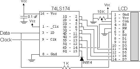
The operation of the resistor/diode "AND" gate may not be immediately obvious. When the shift register bit is low, the diode pulls the connection to the "E" pin low. When the shift register bit is high, the diode will not cause any current flow from the connection at the "E" pin to the shift register. The resistor from "Data" to the "E" pin is a current limiting resistor. When the shift register bit is low and the data bit is high, then the current through the resistor will be limited to 5 mA (for a 5 Volt logic application). At the "Data" side of the resistor, the voltage will still be high, even though the diode is pulling the "E" pin low.

When both the "Data" line and the shift register bit are high, the "E" pin will be high. The "AND" circuit could be a TTL two input AND gate (such as a 7408), if you have an extra one available for your application. When I originally created this circuit, I used the same two transistor and two resistor circuit that I used for the 89C2051 emulator in "Programming and Customizing the 8051 Microcontroller". I saw this "AND" equivalent circuit in an old copy of "Electronics Now" and found that it worked well in this application.

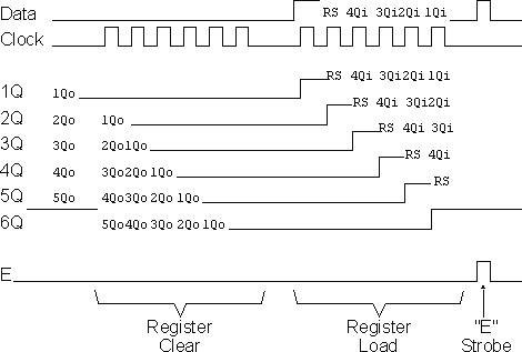
To load the shift register, it first has to be cleared to ensure that the "E" will not be strobed to the LCD inadvertently. This is done by first shifting in six "0"s to make sure that while the correct data is being loaded into the shift register, no "high" voltage level is passed to the "E" pin of the LCD.

Once this is done, the data can be shifted in. The diagram below shows how the shift register is initially cleared and then loaded with the data to be strobed (using "E") into the LCD:

The application code, "2wirelcd.asm" is an assembler source file written for the PIC16C84. The file is written to be used with the "MPASM" assembler built into Microchip's "MPLAB". I wrote the code with the idea that it should be easily portable to any low-end or mid-range PICMicro without modification.

For the two I/O pins ("Data" and "Clock"), I "defined" them to allow you to use virtually any pins in your PICMicro application. I say "virtually any" because PORTA pin 4 (also known as "RA4") is of "open drain" configuration and cannot source a positive voltage. The code itself is a very straightforward example of writing a 4-bit LCD application which displays the string "Hello" on the LCD display. The important difference between this code and a straight 4-bit LCD output is the "NybbleOut" subroutine, which is called twice by each of the "SendCHAR" and "SendINS" subroutines (which send characters and instructions, respectively, to the LCD).

"NybbleOut" first drops the "Data" line and then strobes the "Clock" bit six times to clear the shift register. Next, a "1" is strobed in, followed by the "R/S" pin value, which is stored in the PICMicro's "Carry" flag. I used Carry for this purpose because in this application I used RA0 and RA1 as the output pins and to simplify the operation of the code, I shift PORTA with Carry loaded with the "Data" Pin Value.

If this is not possible in your application, then "NybbleOut" should be changed to the following code. I have marked changed lines with "####' in comments.

NybbleOut2 ; Send a Nybble to the LCD
movwf NOTemp ; Save the Nybble to Shift Out
swapf NOTemp ; Setup to Output to the High Part of the Byte
movlw 6 ; Clear the Shift Register
movwf Dlay

NO2Loop1
ClockStrobe
decfsz Dlay
goto NO2Loop1
movlw 5 ; #### - Now, Shift out the Data with the "RS" Bit
movwf Dlay
bsf Data ; Put out the Gate Bit
ClockStrobe

NO2Loop2
bcf Data ; #### - Clear the Data Bit (which is the Clock)
btfsc STATUS, C ; #### - If the Bit to be output is a "1", Shift it Out
bsf Data
ClockStrobe
rlf NOTemp ; #### - Shift the Next Bit into the Carry Flag
decfsz Dlay
goto NO2Loop2

EStrobe ; Strobe out the LCD Data

return

The only point to notice with this code is that the "E" strobe will become active on the last bit if the least significant data bit is high. This lack of "settling time" before "E" is active does violate the "true" 44780 specification, but I haven't found it to be a problem when I've built this circuit